

Extended finite element simulation of the influence ofnew-cracks on the propagation of fault spontaneous ruptures across stepover
-
摘要:
采用扩展有限元方法计算了断层阶区内介质产生的新生破裂对地震破裂跨越断层阶区传播过程的影响。模型中新生的断层扩展遵循最大剪应力破坏准则,当最大剪应力超过岩石的承受极限时,完整介质产生破裂形成新的断层,并且新断层的扩展方向为最大剪应力方向。扩展有限元法模拟结果表明,断层阶区内新生的断层改变了断层阶区的几何形态,同时也改变了断层破裂后的应力状态。新生破裂可以改变库仑应力在空间的分布格局,特别是可以提高断层上的应力水平,从而提高地震破裂跨越断层阶区的能力。模拟结果还显示,断层阶区内新生破裂的产生,可以使得地震破裂跨越10 km宽的断层阶区,若阶区内部介质没有产生新生破裂,则地震破裂无法跨越该断层阶区。本研究有助于进一步认识地震破裂跨越断层阶区的传播过程,特别是对地震震源过程分析及地震灾害评估等具有重要的科学意义。
Abstract:The step over plays a significant controlling role in the propagation process of seismic rupture. Researchers, based on geological survey results of multiple strike-slip earthquakes globally, have indicated that it is challenging for seismic rupture to cross step over wider than 5 km. Results from numerous numerical simulations also demonstrate that seismic rupture, under conditions such as uniform elastic media and uniform stress fields, cannot extend beyond step over wider than 5 km. However, as research progresses, it has been observed that in few earthquakes, rupture does cross step over wider than 5 km. And research fellows offer various explanations for this phenomenon, including higher stress near step over, changes in material properties due to rock damage, or the presence of concealed faults, among others. Drawing inspiration from previous studies, this paper proposes a novel explanation. In numerical simulations of the seismic rupture process, it is commonly assumed that rupture occurs only on pre-existing faults. Nevertheless, it is highly likely that new ruptures may generate outside pre-existing faults during seismic events, giving rise to new faults. The rocks near step over are relatively brittle and are more likely to generate new ruptures during seismic events, thereby allowing rupture to cross wider step over. This study employs the extended finite element method to investigate the influence of newly generated ruptures near step over on the seismic rupture propagation process. A step over model with a width of 10 km is established. The newly generated ruptures in the model follow the maximum shear stress failure criterion; when the maximum shear stress exceeds the rock’ s ultimate limit, a new fault is formed in the intact medium, and the direction of the new rupture’ s expansion corresponds to the direction of maximum shear stress. According to the results of rock physical experiments, the model medium’ s maximum shear stress limit is set as 72 MPa. The simulation results using the extended finite element method in this study show that after an earthquake occurs, the rupture first propagates to the end of the pre-existing fault, and then new ruptures occur near the step over. The expansion direction of the new rupture is nearly perpendicular to the strike of the pre-existing fault, and the fault continues to expand for 1.8 s, with an expansion length of approximately 8.2 km and an expansion velocity of approximately 4 556 m/s. This study also establishes a model that does not consider newly generated ruptures for comparison. Without considering new ruptures, the rupture cannot cross a 10 km wide step over. The paper compares Coulomb stress distribution maps at a specific moment in these two scenarios. According to the Coulomb stress distribution, it is evident that without considering newly generated ruptures, the rupture in this model can only cross step over for the model approximately 5 km wide. The new ruptures alter the geometry of the step over and greatly change the spatial distribution pattern of Coulomb stress, especially by elevating stress levels on the fault, thereby enhancing the ability of seismic rupture to cross step over and allowing it to cross step over 10 km wide. This study contributes to a deeper understanding of the propagation process of seismic rupture across step over, particularly for seismic source process analysis and seismic hazard assessment.
-
Keywords:
- stepover /
- new-crack /
- spontaneous rupture /
- extended finite element method
-
引言
活动断裂几何形态复杂,并且控制着地震孕育、发生及断层破裂传播的过程(Magistrale,Day,1999;Brune,2002;Ando et al,2004;Oglesby,2008;Lozos,2010)。断层阶区(stepover)是走滑型断裂系统中一种常见的结构。如果地震破裂能跨越断层阶区继续前行,则破裂会传播更远的距离,形成震级更高的地震,释放更多的能量,进而造成更大的地震破坏;若破裂无法跨越断层阶区,则破裂将会在此终止(Wesnousky,2006),相应地造成的地震灾害则可能较轻。因此研究地震破裂能否跨越断层阶区,对于深入认识地震震源过程及震害评估等有着重要的科学意义及应用价值。
前人对于断层阶区影响地震破裂传播过程进行了很多野外观测和数值模拟方面的研究。例如:Knuepfer (1989)根据收集到的全球范围内走滑型地震的调查结果,指出地震破裂无法跨越5 km宽的压缩型断层阶区和8 km宽的拉张型断层阶区;Wesnousky (2006)研究了2002年以前22次走滑型地震的地表破裂特征,发现只有40%的地震破裂能够跨越断层阶区继续传播,且最大跨越宽度为4 km;Segall和Pollard (1980)以及Sibson (1985)用准静态模拟证明了地震破裂更容易跨越拉张型断层阶区;Harris和Day (1993)采用有限差分方法模拟了二维情况下破裂在具有阶区的两条平行断层中的动态传播过程,并通过库仑应力的空间分布判断不同应力场和摩擦系数下破裂能够跨越的断层阶区最大宽度,结果显示破裂无法跨越超过5 km宽的断层阶区。此外,大量的研究人员通过数值模拟分析(Kase,Kuge,1998;Harris,Day,1999;Harris et al,2002;袁杰,朱守彪,2014)也证实,破裂无法跨越宽度超过5 km的断层阶区继续传播。
然而,随着观测设备、监测方法以及破裂反演等研究的不断深入,科研人员发现了与上述研究结果不同的现象,即地震破裂可以跨越更宽的断层阶区(Yang et al,2019a,b;Yao,Yang,2020)。例如:在1992年加利福利亚MW7.3兰德斯(Landers)地震中,破裂跨越了6 km宽的断层阶区(Wald,Heaton,1994);在2001年昆仑山口西MW7.8地震中,地震破裂可以跨越10 km宽的断层阶区,该断层阶区位于太阳湖断层与库塞湖断层之间(Lin et al,2002;Xu et al,2002,2006;万永革等,2008);在2016年新西兰MW7.8凯库拉(Kaikoura)地震中,破裂跨越了7 km宽的断层阶区(Bradley et al,2017)。同时,数值模拟结果也显示,地震破裂可以跨越更宽的断层阶区。例如:Duan和Oglesby (2006)采用黏弹性介质模型研究了30次地震循环过程中断层阶区的应力场演化,以及每次地震破裂在阶区附近的动态传播过程,提出在经历多次地震后断层阶区附近出现应力不均匀,进而使得破裂能够跨越超过8 km宽的断层阶区;Wang等(2020)通过施加不均匀的初始应力场,发现地震破裂可以跨越20 km宽的膨胀型断层阶区。
Lozos等(2012)研究了断层阶区之间存在的小尺度中间断层对破裂传播过程的控制作用,指出中间断层的长度对断层阶区的破裂传播过程有很大影响。Finzi和Langer (2012)分析了断层阶区内岩石损伤对破裂传播过程的作用,结果表明在不同情况下,断层阶区内岩石损伤有可能促使地震破裂跨越更宽的断层阶区,但也有可能导致较窄的断层阶区阻止破裂的继续传播。
受到上述研究(Finzi,Langer,2012;Lozos et al,2012)的启示,本文拟在断层阶区内设置损坏区(即可以产生新生破裂的区域),利用扩展有限元方法(extended finite element method,缩写为XFEM)模拟地震破裂跨越断层阶区时的传播特征,以此来考察新生破裂的形成及破裂跨越更宽的断层阶区的条件。
1. 方法与模型
有限元模拟中,通过预先设定的破坏准则,程序可以自动判定新生断层扩展开始的时间、扩展方向以及扩展长度等。实际计算时,采用最大剪应力破坏准则模拟新破裂的产生,即当岩石最大剪应力达到极限值$ {k}_{\mathrm{T}} $时岩石开始产生新断层,然后断层扩展并传播(Chu et al,2015;Childs et al,2017)。
1.1 扩展有限单元法的基本数学表达式
扩展有限元方法通过带有不连续性质的扩充形函数(enrichment functions)来描述单元格内部的不连续场。为了降低计算量,扩展有限元技术利用单位分解法(partition of unity method,缩写为PUM)(Melenk,Babuška,1996)将位移场$ {{\boldsymbol{u}}} $分解为如下形式:
$$ {{\boldsymbol{u}}}=\sum _{I}{N}_{I}{ ( {\boldsymbol{x}} ) {\boldsymbol{u}}}_{I}+\sum _{J}{N}_{J} ( {\boldsymbol{x}} ) \varPhi ( {\boldsymbol{x}} ) {q}_{J} \text{,} $$ (1) 式中,右端第一项为标准有限元近似,第二项为扩充项近似,$ {N}_{I} ( {\boldsymbol{x}} ) $和$ {N}_{J} ( {\boldsymbol{x}} ) $为插值形函数,满足$ \sum _{I}{N}_{I} ( {\boldsymbol{x}} ) =1 $和$ \sum _{J}{N}_{J} ( {\boldsymbol{x}} ) =1 $,$ {q}_{J} $为单元节点增加的额外自由度。为了简便,$ {N}_{J} ( {\boldsymbol{x}} ) \varPhi ( {\boldsymbol{x}} ) $可直接写为$ {\psi }_{J} ( {\boldsymbol{x}} ) $。为增加收敛速度,构造的形函数需要考虑位移场$ {{\boldsymbol{u}}} $的某些特性。
水平集函数(level set function)$ f ( {\boldsymbol{x}} ) $可以描述裂纹面$ {\mathcal{T}}_{{\mathrm{c}}}^{0} $的几何形态(Osher,Sethian,1988;Barth,Sethian,1998;Sethian,1999;Stolarska et al,2001;Moës et al,2002),在裂纹两侧函数的符号相反。
$$ f ( {\boldsymbol{x}} ) =\underset{\overline{{\boldsymbol{x}}}\in {\mathcal{T}}_{{\mathrm{c}}}^{0}}{\rm{min}}\left\|{\boldsymbol{x}}-\overline{{\boldsymbol{x}}}\right\| {\mathrm{sign}} ( \,\,{{\boldsymbol{n}}}^+ ( {\boldsymbol{x}}-\overline{{\boldsymbol{x}}} ) ) \text{,} $$ (2) 式中,$ {\boldsymbol{n}}^{+} $是裂纹$ {\mathcal{T}}_{\mathrm{c}}^{0} $的单位法向量,$ f ( {\boldsymbol{x}} ) $的大小为$ {\boldsymbol{x}}\mathrm{点} $到裂纹的最短距离,如果x与$ {\boldsymbol{n}}^{+} $方向相同,$ f ( {\boldsymbol{x}} ) $取正值,如果x与$ {\boldsymbol{n}}^{+} $方向相反,则$ f ( {\boldsymbol{x}} ) $取负值。
被裂纹完全穿过的单元节点设为集合$ {S}_{{\mathrm{k}}} $,裂纹尖端周围的节点设为集合$ {S}_{{\mathrm{c}}} $,这两种情况下单元集合位移场的计算方法有所不同。综合这两种情况,位移场$ {{\boldsymbol{u}}}$的单位分解(李录贤,王铁军,2005)表达式可写为:
$$ \begin{split} {{\boldsymbol{u}}}=\sum _{I}{N}_{I}{ ( {\boldsymbol{x}} ) {\boldsymbol{u}}}_{I}+\sum _{J\in{S}_{{\mathrm{k}}}}{N}_{J} ( {\boldsymbol{x}} ) H ( f ( {\boldsymbol{x}} ) ) {a}_{J} ( t ) +\sum _{K\in{S}_{{\mathrm{c}}}}{N}_{K} ( {\boldsymbol{x}} ) \varPhi ( {\boldsymbol{x}} ) {b}_{K} ( t ) \text{,} \end{split}$$ (3) 式中,$ {a}_{J} $和$ {b}_{K} $均为节点附加自由度,$ H ( {\boldsymbol{x}} ) $为阶跃函数。
1.2 有限元模型
为保证计算精度,并尽量减少节点的数量,提高计算效率,模型几何选为包含断层阶区的100 km×100 km的正方形。断层附近的单元长度设置为100 m,远离断层阶区的单元尺寸逐渐增加到500 m。模型的四周设置了吸收边界,从而防止地震波在边界处的反射影响计算结果(Gerdes,2000;Cui,Zhu,2022)。由于研究区域较小,模拟中的初始应力场假定为均匀。初始应力场、介质物性等模型参数列于表1。本文采用隐式动力学方法,计算的时间步长为0.01 s。计算中,新裂纹的产生遵循最大剪应力破坏准则。根据前人的研究(王鹏等,2005;刘书文,2021)以及数值模拟,本研究设置岩石的最大剪应力极限为72 MPa。为了节省计算时间,仅在断层阶区之间设置了损伤区(可以产生新断层的区域)。此外,破裂传播受滑移弱化的摩擦关系(Ida,1972;Andrews,1976;朱守彪,袁杰,2018)控制,摩擦本构关系中的参数设置为静摩擦系数0.6,动摩擦系数0.5,特征滑移距离0.1 m。
表 1 模型参数Table 1. Model parameters初始正应力
σ/MPa初始剪应力
τ/MPa横波速度
vS/(m·s−1)纵波速度
vP/(m·s−1)介质密度
ρ/(kg·m−3)成核区长度
/km岩石承受的最大剪应力
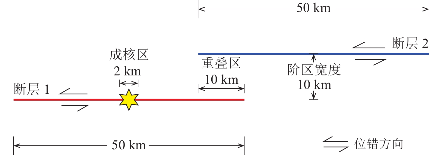
/MPa100 56 5 959 3 294 2 700 2 72 为了突出重点,简化计算,将模型中断层阶区的几何设置为图1所示,断层1和断层2的长度均为50 km,两条断层间的距离为10 km,它们之间存在一个10 km长的重叠区。为了使断层产生自发破裂,在断层1中部设置了长约2 km的成核区。
2. 计算结果
为了对比研究断层阶区内介质是否发生新的断层破裂及其对破裂在断层阶区内传播过程的影响,本文建立了两个模型(图2,3)。模型1不考虑阶区内介质的新生破裂,模型2则考虑断层阶区内的介质产生的新破裂。两个模型中的其它参数(初始应力场、摩擦本构关系以及介质物性等)均完全相同。对于沿着先存断层的破裂过程本文基于传统有限元方法模拟计算,而对于断层阶区内的新生裂纹扩展过程则利用本文介绍的扩展有限元方法进行计算。
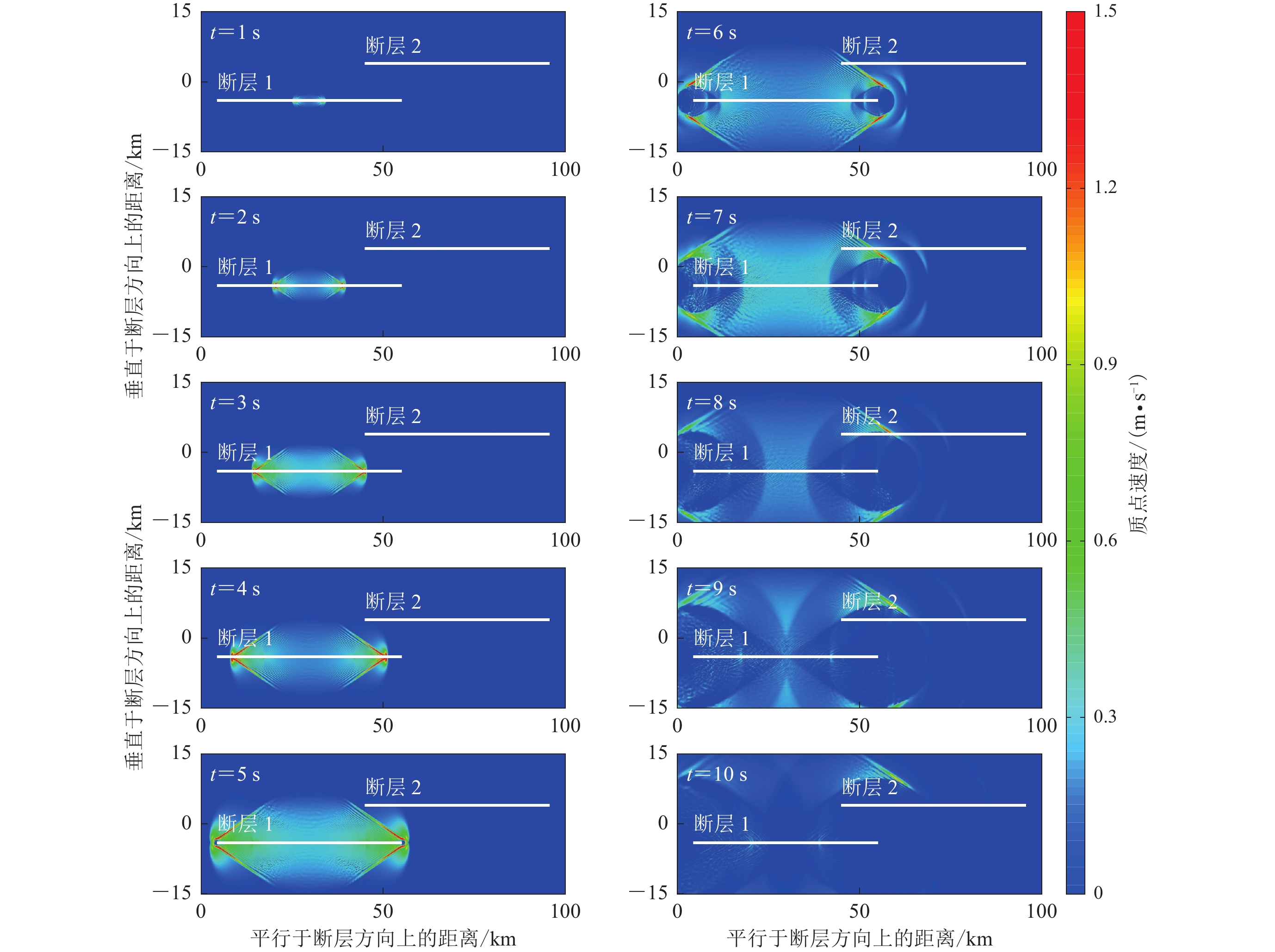
![]() 图 2 模型1中断层破裂在不同时刻质点振动速度等值线云图的快照Figure 2. Snap shots of spatial contour distributions of particle velocities at different times in fault rupture propagation in Model 1
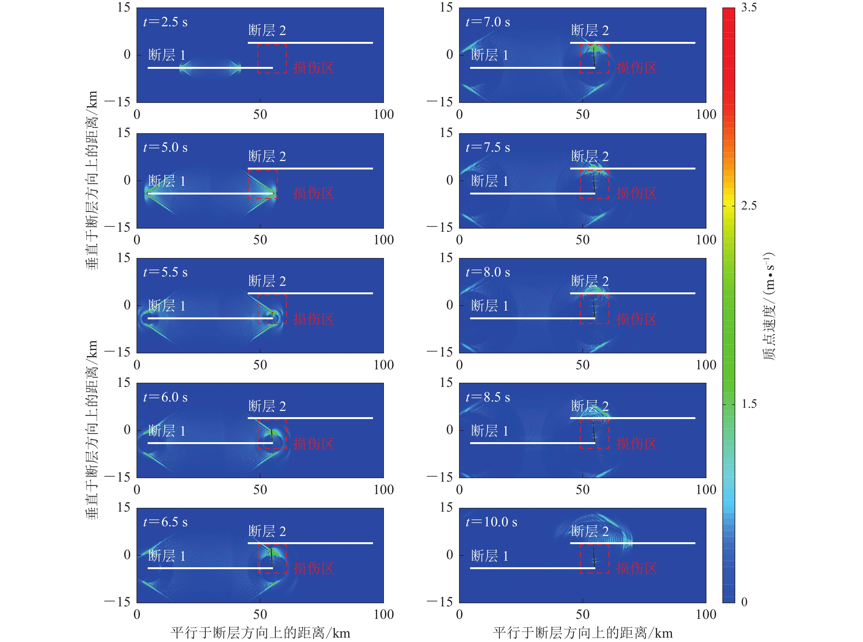
图 2 模型1中断层破裂在不同时刻质点振动速度等值线云图的快照Figure 2. Snap shots of spatial contour distributions of particle velocities at different times in fault rupture propagation in Model 1![]() 图 3 模型2中断层破裂传播过程中,不同时刻质点振动速度等值线云图快照图中黑线表示新产生的断层 (下同),长度大约8.2 km,方向与断层1和断层2几乎垂直Figure 3. Contour distributions of particle velocities at different time in fault rupture propagation in Model 2The newly-created fault is shown as black line (the same below),and it is about 8.2 km long and is almost perpendicular to the strikes of faults 1 and 2
图 3 模型2中断层破裂传播过程中,不同时刻质点振动速度等值线云图快照图中黑线表示新产生的断层 (下同),长度大约8.2 km,方向与断层1和断层2几乎垂直Figure 3. Contour distributions of particle velocities at different time in fault rupture propagation in Model 2The newly-created fault is shown as black line (the same below),and it is about 8.2 km long and is almost perpendicular to the strikes of faults 1 and 22.1 不考虑断层阶区内新生破裂的模拟结果
模型1不考虑阶区内介质出现新生破裂。破裂在断层1上成核后,立即沿着断层1向两侧扩展、产生自发传播。图2给出了断层及周边质点振动速度的等值线云图在不同时刻的快照。图中显示,破裂开始于断层1的中部(成核位置),传播到断层1右侧末端时需要的时间为4.7 s,可以计算其传播速度为5 208 m/s,该速度超过了剪切波速度(vS=3 294 m/s),因此为超剪切破裂。此外,图中还清楚地显示,破裂未能跨越断层阶区而继续传播,断层2始终处于闭锁状态。模型1的计算结果与前人的研究结果(Harris et al,2002;Wesnousky,2006)一致,即破裂无法跨跃宽度超过5 km的断层阶区而继续传播。
2.2 考虑断层阶区内介质产生新生破裂的模拟结果
模型2与模型1的情况几乎完全相同。不同的是,在模型2中断层阶区内设置了介质可以发生损伤产生新裂纹的区域,并且利用扩展有限元方法来模拟断层阶区内新破裂的产生以及断层的扩展传播过程。众所周知,破裂在传播过程中,要改变周边介质的应力状态,若最大剪应力超过了岩石的承受极限,岩石将产生破坏,生成新的裂纹,并且新破裂的扩展方向为最大剪应力的方向(基于规定的破裂准则)。但最大剪应力存在相互垂直的两个方向,在实际情况中新破裂可能沿着其中任意一个方向扩展,也可能在两个方向上都发生扩展(与应力状态有关)。在模型2中,初始应力场的最大剪应力方向分别为平行于和垂直于断层的走向。断层的破裂传播会改变断层端部的应力场,使新的最大剪应力的方向发生变化,但是经过计算发现这种变化十分微小。新的最大剪应力依然分别垂直和平行于断层1的走向。如果断层继续沿着原来的方向扩展,那么只是增加了重叠区的长度,对是否触发断层2产生破裂影响较小。如果断层沿着垂直方向扩展,则等价于断层2与新破裂之间的距离减小,这样就有利于破裂跨越断层阶区而继续前行。同时,它们之间的夹角也由0°变为90°,这会极大地促进破裂在断层阶区内的传播过程。
图3为模型2中断层破裂传播过程中质点振动速度在不同时刻的快照。红色虚线框表示岩石损伤区域。断层阶区之间是可以产生裂纹的“软弱区”(Finzi,Langer,2012),本文只在断层阶区之间设置了损伤区域,可以产生新的破裂。新生破裂只发生在该区域,超出该区域即使满足了最大剪应力破坏准则也不会产生新破裂。由于在模型1和模型2中断层1上的破裂过程是完全相同的,因此在此详细展示破裂在阶区内及附近的传播情况。图3显示,在破裂传播至断层1右侧端部时,应力升高,使得最大剪应力超过了岩石的承受极限,断层1的端部开始产生新的破裂,然后新破裂不断扩展。
图4为断层阶区附近的质点振动速度云图,图中可以清晰地看到新生断层扩展的过程。新生断层的扩展大概开始于4.8 s,扩展方向几乎与断层1的走向垂直。在6.6 s左右新生断层的扩展结束,扩展长度约为8.2 km。因此新生断层扩展速度大约为4 556 m/s,新断层同样为左旋走滑,破裂速度也超过了剪切波速度,从图中可以看到新生断层两侧地震波叠加而形成的马赫锥。新生断层的传播进一步改变了原来的断层几何及原应力状态。图中显示,新产生的断层距离断层2只有1.8 km,断层端部的应力触发了断层2产生自发破裂。断层2的破裂开始于6.9 s,破裂产生的地震波与新生断层扩展产生的地震波重合使其不易分辨,在10.0 s之后可以清楚地看到断层2破裂产生的马赫波。模型2的计算结果说明如果在破裂过程中存在新生断层扩展,并且若扩展的方向和长度合适,破裂就有可能会跨越那些原本会阻碍破裂传播的断层阶区,进而形成更长距离的断层破裂,形成更大震级的地震事件,造成更为严重的地震灾害。
![]() 图 4 模型2中不同时刻新生断层扩展长度的变化Figure 4. Variation of the length of newly-generated fault at different time in Model 2
图 4 模型2中不同时刻新生断层扩展长度的变化Figure 4. Variation of the length of newly-generated fault at different time in Model 23. 讨论
模型2的计算结果说明新生断层扩展增加了地震破裂跨越断层阶区的最大宽度。但是,为什么在断层阶区内产生了新生破裂就可以导致地震破裂更容易呢?下面我们从地震破裂过程中断层面上及附近区域库仑应力的空间分布及其演化过程来进一步讨论这个力学问题。
库仑应力${{\sigma }}_{\mathrm{f}} $的空间分布及其随着时间的变化可以用来判断断层是否会发生破裂(Harris,Day,1993;袁杰,朱守彪,2014)。库仑应力的表达式为
$$ {{\sigma }_{{\mathrm{f}}}=\tau -\mu }_{{\mathrm{s}}}\sigma \text{,} $$ (4) 式中,τ为断层面上的剪应力,σ为断层面上的正应力,μs为静摩擦系数。如果断层位于库仑应力大于零的区域,断层上的剪应力超过摩擦力所能承受的极限,断层就会开始滑动(Zhu,Zhang,2013;袁杰,朱守彪,2014;Zhu,Miao,2015)。反之,在库仑应力小于零的区域,断层处于闭锁状态。
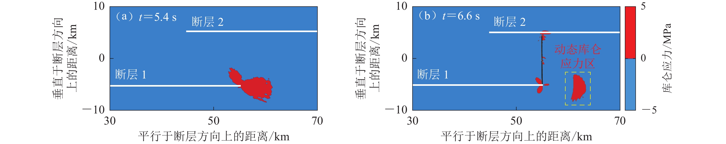
我们选取与断层1及断层2走向平行的面作为计算库仑应力的投影面。图5展示了模型中计算的库仑应力的空间分布。在模型1中,断层1上的破裂终止后,断层1端部的库仑应力逐渐趋于稳定,在5.4 s之后库仑应力几乎不再改变。图5a给出了模型1在5.4 s时的库仑应力空间分布图。图中显示,库仑应力大于零的区域集中在断层1尖端附近,断层2上的库仑应力小于0,因而断层2处于闭锁状态,不会产生地震破裂,即地震破裂只是在断层1上传播,无法跨越断层阶区。但在模型2中,新生断层扩展结束后,新生断层端部的库仑应力会逐渐演化,然后渐渐趋于稳定。我们关注的是断层2开始破裂时断层阶区内的库仑应力分布情况,所以选取7.0 s时的库仑应力空间分布(图5b)来进行分析。图中库仑应力大于零的区域主要包含两部分:一部分是黄色虚线框内的库仑应力,这是由破裂形成的应力波产生的动态部分;另一部分在断层端部附近,因应力集中而产生。受新生断层扩展的影响,断层1末端库仑应力正值区域不断减小,并且产生了动态移动的库仑应力正值区。新生断层末端的应力集中使得断层2的断层面上及附近区域的库仑应力为正值,从而触发了断层2产生自发破裂。
![]() 图 5 模型1 (a)和模型2 (b)中库仑应力空间分布图Figure 5. The spatial distributions of Coulomb stresses in Model 1 and 2
图 5 模型1 (a)和模型2 (b)中库仑应力空间分布图Figure 5. The spatial distributions of Coulomb stresses in Model 1 and 2总之,上述计算结果表明,模型2中断层阶区内部由于产生了新生破裂,断层阶区的断层几何及应力场均发生了改变,从而使得地震破裂可以跨越更宽的断层阶区,产生更大震级的地震。但是,实际情况非常复杂,断层阶区内不仅可以产生新生破裂,阶区内部应力场的空间分布还存在不均匀性,介质物理性质的不均匀或各向异性等诸多因素都有可能影响破裂跨越断层阶区的宽度。对此,还需要今后开展深入研究。
4. 结论
本文采用扩展有限元方法计算了断层阶区内产生新生破裂对地震破裂跨越断层阶区的影响。主要得到如下初步结果:
1) 当断层阶区内部介质不产生新生破裂时,地震破裂无法跨越宽度超过10 km的断层阶区,由此进一步验证了前人的结论;
2) 当断层阶区内介质产生了新生破裂时,库仑应力在空间的分布发生变化,使得断层2上的库仑应力增加,从而促进地震破裂跨越更宽的断层阶区,产生更大震级的地震;
3) 断层阶区内产生的新生破裂等价于断层阶区的断层阶距(宽度)缩短,从而有利于地震破裂跨越更宽的阶区而继续传播。
-
![]()
图 4 模型2中不同时刻新生断层扩展长度的变化
Figure 4. Variation of the length of newly-generated fault at different time in Model 2
![]()
图 2 模型1中断层破裂在不同时刻质点振动速度等值线云图的快照
Figure 2. Snap shots of spatial contour distributions of particle velocities at different times in fault rupture propagation in Model 1
![]()
图 3 模型2中断层破裂传播过程中,不同时刻质点振动速度等值线云图快照
图中黑线表示新产生的断层 (下同),长度大约8.2 km,方向与断层1和断层2几乎垂直
Figure 3. Contour distributions of particle velocities at different time in fault rupture propagation in Model 2
The newly-created fault is shown as black line (the same below),and it is about 8.2 km long and is almost perpendicular to the strikes of faults 1 and 2
![]()
图 5 模型1 (a)和模型2 (b)中库仑应力空间分布图
Figure 5. The spatial distributions of Coulomb stresses in Model 1 and 2
表 1 模型参数
Table 1 Model parameters
初始正应力
σ/MPa初始剪应力
τ/MPa横波速度
vS/(m·s−1)纵波速度
vP/(m·s−1)介质密度
ρ/(kg·m−3)成核区长度
/km岩石承受的最大剪应力
/MPa100 56 5 959 3 294 2 700 2 72  下载: 导出CSV
-
李录贤,王铁军. 2005. 扩展有限元法(XFEM)及其应用[J]. 力学进展,35(1):5–20. doi: 10.3321/j.issn:1000-0992.2005.01.002 Li L X,Wang T J. 2005. The extended finite element method and its applications:A review[J]. Advances in Mechanics,35(1):5–20 (in Chinese).
刘书文. 2021. 循环荷载作用下不同强度岩石动力特性实验研究[D]. 衡阳:南华大学:40−49. Liu S W. 2021. Experimental Study on Dynamic Characteristics of Rocks With Different Strength under Cyclic Loading[D]. Hengyang:University of South China:40−49 (in Chinese).
万永革,沈正康,王敏,张祖胜,甘卫军,王庆良,盛书中. 2008. 根据GPS和InSAR数据反演2001年昆仑山口西地震同震破裂分布[J]. 地球物理学报,51(4):1074–1084. doi: 10.3321/j.issn:0001-5733.2008.04.016 Wan Y G,Shen Z K,Wang M,Zhang Z S,Gan W J,Wang Q L,Sheng S Z. 2008. Coseismic slip distribution of the 2001 Kunlun mountain pass west earthquake constrained using GPS and InSAR data[J]. Chinese Journal of Geophysics,51(4):1074–1084 (in Chinese).
王鹏,李安贵,蔡美峰,杨同. 2005. 基于随机-模糊理论的岩石抗剪强度参数的确定[J]. 岩石力学与工程学报,24(4):547–552. doi: 10.3321/j.issn:1000-6915.2005.04.001 Wang P,Li A G,Cai M F,Yang T. 2005. Random-fuzzy monovariant linear regression method for determining the shear strength parameters of rock[J]. Chinese Journal of Rock Mechanics and Engineering,24(4):547–552 (in Chinese).
袁杰,朱守彪. 2014. 断层阶区对震源破裂传播过程的控制作用研究[J]. 地球物理学报,57(5):1510–1521. doi: 10.6038/cjg20140515 Yuan J,Zhu S B. 2014. Effects of stepover on rupture propagation[J]. Chinese Journal of Geophysics,57(5):1510–1521 (in Chinese).
朱守彪,袁杰. 2018. 2008年汶川大地震中北川地区极重震害的物理机制研究[J]. 地球物理学报,61(5):1863–1873. doi: 10.6038/cjg2018M0111 Zhu S B,Yuan J. 2018. Physical mechanism for extremely serious seismic damage in the Beichuan area caused by the great 2008 Wenchuan earthquake[J]. Chinese Journal of Geophysics,61(5):1863–1873 (in Chinese).
Ando R,Tada T,Yamashita T. 2004. Dynamic evolution of a fault system through interactions between fault segments[J]. J Geophys Res: Solid Earth,109(B5):B05303.
Andrews D J. 1976. Rupture velocity of plane strain shear cracks[J]. J Geophys Res,81(32):5679–5687. doi: 10.1029/JB081i032p05679
Barth T J,Sethian J A. 1998. Numerical schemes for the Hamilton-Jacobi and level set equations on triangulated domains[J]. J Comput Phys,145(1):1–40. doi: 10.1006/jcph.1998.6007
Bradley B A,Razafindrakoto H N T,Nazer M A. 2017. Strong ground motion observations of engineering interest from the 14 November 2016 MW7.8 Kaikoura,New Zealand earthquake[J]. Bull NZ Soc Earthq Eng,50(2):85–93.
Brune J N. 2002. Precarious-rock constraints on ground motion from historic and recent earthquakes in southern California[J]. Bull Seismol Soc Am,92(7):2602–2611. doi: 10.1785/0120000606
Childs C,Holdsworth R E,Jackson C A L,Manzocchi T,Walsh J J,Yielding G. 2017. Introduction to the geometry and growth of normal faults[J]. Geol Soc Lond, Spec Publ,439:1–9. doi: 10.1144/SP439.24
Chu S S,Lin M L,Huang W C,Nien W T,Liu H C,Chan P C. 2015. Simulation of growth normal fault sandbox tests using the 2D discrete element method[J]. Comput Geosci,74:1–12. doi: 10.1016/j.cageo.2014.10.006
Cui Z F,Zhu S B. 2022. Effect of real-world frictional strengthening layer near the Earth’s free surface on rupture characteristics with different friction laws:Implication for scarcity of supershear earthquakes[J]. Tectonophysics,837:229447. doi: 10.1016/j.tecto.2022.229447
Duan B C,Oglesby D D. 2006. Heterogeneous fault stresses from previous earthquakes and the effect on dynamics of parallel strike-slip faults[J]. J Geophys Res: Solid Earth,111(B5):B05309.
Finzi Y,Langer S. 2012. Predicting rupture arrests,rupture jumps and cascading earthquakes[J]. J Geophys Res: Solid Earth,117(B12):B12303.
Gerdes K. 2000. A review of infinite element methods for exterior Helmholtz problems[J]. J Comput Acoust,8(1):43–62. doi: 10.1142/S0218396X00000042
Harris R A,Day S M. 1993. Dynamics of fault interaction:Parallel strike-slip faults[J]. J Geophys Res: Solid Earth,98(B3):4461–4472. doi: 10.1029/92JB02272
Harris R A,Day S M. 1999. Dynamic 3D simulations of earthquakes on en echelon faults[J]. Geophys Res Lett,26(14):2089–2092. doi: 10.1029/1999GL900377
Harris R A,Dolan J F,Hartleb R,Day S M. 2002. The 1999 Izmit,Turkey,earthquake:A 3D dynamic stress transfer model of intra earthquake triggering[J]. Bull Seismol Soc Am,92(1):245–255. doi: 10.1785/0120000825
Ida Y. 1972. Cohesive force across the tip of a longitudinal-shear crack and Griffith’s specific surface energy[J]. J Geophys Res,77(20):3796–3805. doi: 10.1029/JB077i020p03796
Kase Y,Kuge K. 1998. Numerical simulation of spontaneous rupture processes on twonon-coplanar faults:The effect of geometry on fault interaction[J]. Geophys J Int,135(3):911–922. doi: 10.1046/j.1365-246X.1998.00672.x
Knuepfer P L K. 1989. Implications of the Characteristics of End-Points of Historical Surface Fault Ruptures for the Nature of Fault Segmentation[R]. California:United States Geological Survey:193−228.
Lin A M,Fu B H,Guo J M,Zeng Q L,Dang G M,He W G,Zhao Y. 2002. Co-seismic strike-slip and rupture length produced by the 2001 MS8.1 Central Kunlun earthquake[J]. Science,296(5575):2015–2017. doi: 10.1126/science.1070879
Lozos J C. 2010. The Effects of Strike-Slip Fault Stepovers on Rupture Behavior and Ground Motion Distribution[D]. California:University of California:22−67.
Lozos J C,Oglesby D D,Brune J N,Olsen K B. 2012. Small intermediate fault segments can either aid or hinder rupture propagation at stepovers[J]. Geophys Res Lett,39(18):l18305.
Magistrale H,Day S. 1999. 3D simulations of multi-segment thrust fault rupture[J]. Geophys Res Lett,26(14):2093–2096. doi: 10.1029/1999GL900401
Melenk J M,Babuška I. 1996. The partition of unity finite element method:Basic theory and applications[J]. Comput Methods Appl Mech Eng,139(1/2/3/4):289–314.
Moës N,Gravouil A,Belytschko T. 2002. Non-planar 3D crack growth by the extended finite element and level sets,Part I:Mechanical model[J]. Int J Numer Meth Eng,53(11):2549–2568. doi: 10.1002/nme.429
Oglesby D. 2008. Rupture termination and jump on parallel offset faults[J]. Bull Seismol Soc Am,98(1):440–447. doi: 10.1785/0120070163
Osher S,Sethian J A. 1988. Fronts propagating with curvature-dependent speed:Algorithms based on Hamilton-Jacobi formulations[J]. J Comput Phys,79(1):12–49. doi: 10.1016/0021-9991(88)90002-2
Segall P,Pollard D D. 1980. Mechanics of discontinuous faults[J]. J Geophys Res: Solid Earth,85(B8):4337–4350. doi: 10.1029/JB085iB08p04337
Sethian J A. 1999. Level Set Methods and Fast Marching Methods:Evolving Interfaces in Computational Geometry,Fluid Mechanics,Computer Vision,and Materials Science[M]. 2nd ed. Cambridge:Cambridge University Press:15−42.
Sibson R H. 1985. Stopping of earthquake ruptures at dilational fault jogs[J]. Nature,316(6025):248–251. doi: 10.1038/316248a0
Stolarska M,Chopp D L,Moës N,Belytschko T. 2001. Modelling crack growth by level sets in the extended finite element method[J]. Int J Numer Meth Eng,51(8):943–960. doi: 10.1002/nme.201
Wald D J,Heaton T H. 1994. Spatial and temporal distribution of slip for the 1992 Landers,California,earthquake[J]. Bull Seismol Soc Am,84(3):668–691. doi: 10.1785/BSSA0840030668
Wang H,Liu M,Duan B C,Cao J L. 2020. Rupture propagation along stepovers of strike-slip faults:Effects of initial stress and fault geometry[J]. Bull Seismol Soc Am,110(3):1011–1024. doi: 10.1785/0120190233
Wesnousky S G. 2006. Predicting the endpoints of earthquake ruptures[J]. Nature,444(7117):358–360. doi: 10.1038/nature05275
Xu X W,Chen W B,Ma W T,Yu G H,Chen G H. 2002. Surface rupture of the Kunlunshan earthquake ( MS8.1),northern Tibetan Plateau,China[J]. Seismol Res Lett,73(6):884–892. doi: 10.1785/gssrl.73.6.884
Xu X W,Yu G H,Klinger Y,Tapponnier P,van der Woerd J. 2006. Reevaluation of surface rupture parameters and faulting segmentation of the 2001 Kunlunshan earthquake ( MW7.8),northern Tibetan Plateau,China[J]. J Geophys Res: Solid Earth,111(B5):B05316.
Yang H F,Yao S L,He B,Newman A V. 2019a. Earthquake rupture dependence on hypocentral location along the Nicoya Peninsula subduction megathrust[J]. Earth Planet Sci Lett,520:10–17. doi: 10.1016/j.jpgl.2019.05.030
Yang H F,Yao S L,He B,Newman A V,Weng H H. 2019b. Deriving rupture scenarios from interseismic locking distributions along the subduction megathrust[J]. J Geophys Res: Solid Earth,124(10):10376–10392. doi: 10.1029/2019JB017541
Yao S L,Yang H F. 2020. Rupture dynamics of the 2012 Nicoya MW7.6 earthquake:Evidence for low strength on the megathrust[J]. Geophys Res Lett,47(13):e2020GL087508. doi: 10.1029/2020GL087508
Zhu S,Zhang P. 2013. Fem simulation of interseismic and coseismic deformation associated with the 2008 Wenchuan earthquake[J]. Tectonophysics,584:64–80. doi: 10.1016/j.tecto.2012.06.024
Zhu S,Miao M. 2015. How did the 2013 Lushan earthquake ( MS=7.0) trigger its aftershocks? Insights from static Coulomb stress change calculations[J]. Pure Appl Geophy,172(10):2481–2494. doi: 10.1007/s00024-015-1064-3

计量
- 文章访问数: 145
- HTML全文浏览量: 41
- PDF下载量: 58
